UNIT:14
Electrical circuits: Electricity and Magnetism
| Physics 12 | Complete CURRICULUM |
|---|---|
| 14.1 | Understand Kirchhoff’s law as well as use it to calculate unknown parameters in electrical circuits |
| 14.2 | Describe the circuit diagram and working of the Wheatstone bridge circuit and Understand its importance in the real situation |
| 14.3 | Describe Meter bridge and understand it |
| 14.4 | Know the construction, working and importance of potentiometer |
| 14.5 | Understand the concepts of superconductors |
| 14.6 | Know the meaning of perfect conductors and distinguish it from superconductors |
| 14.7 | Learn the technique to covert galvanometer into voltmeter and ammeter |
| Physics NEB | Scope and sequence |
|---|---|
| 14.1 | 14.1 Kirchhoff’s Law |
| 14.2 | 14.2 Wheatstone bridge circuit; Meter bridge |
| 14.3 | 14.3 Potentiometer: Comparison of e.m.f., measurement of internal resistance of a cell |
| 14.4 | 14.4 Superconductors; Perfect conductors |
| 14.5 | 14.5 Conversion of galvanometer into voltmeter and ammeter ; Ohmmeter |
| 14.6 | 14.6 Joule’s law |
Complete Class 12 Physics Electrical Circuits Notes for NEB Board Exam.
The rate of flow of electrons in a conductor is called Electric current.
The path for transmitting Electric current is an Electric circuit.
14.1 Kirchhoff’s Laws
1.Kirchhoff ’s Current Law (KCL) or the Junction Rule:
KCL states that the algebraic sum of currents at a junction of an electric circuit is zero. i.e. |
| Fig: Kirchhoff's current law |
Sign Conventions for KCL:
- Current entering the junction(node) is considered positive.
- Current leaving the junction is considered negative.
Suppose currents I1, I5, and I4are entering the junction, and the currents I2and I3leaving the junction as shown in the figure alongside. Then using the sign convention, KCL for this case can be written as:
Or, Total current entering the junction = Total current leaving the junction
#KCL is based on the law of conservation of charge or the non-accumulation of charge.
(note: accumulation of charge means when two conductors come together then the electron flow from one another and one will have more electrons than the other and positive and negative charges are developed = accumulation of charge.
due to this phenomenon like lighting occurs)
2. Kirchhoff's Voltage law (KVL) or loop rule
KVL states that " the sum of potential differences around a closed loop of a circuit must be zero. "
In other words, "The algebraic sum of EMFs(E) in any closed circuit must be equal to the algebraic sum of the product of current(I) and resistance(R) in the loop." i.e.
#KVL is based on the law of conservation of energy.
Sign Conventions for KVL:
First of all choose a direction of circling a loop, either clockwise or counterclockwise. Then, use the following conventions:
❖ In case of cell in the loop:
1. If the direction of the current is from positive to negative terminal as shown in fig(1), the EMF of a cell is taken as negative(-E).
,the%20EMF%20of%20a%20cell%20is%20taken%20as%20negative(-.jpeg) |
| Fig(1) |
2. If the direction of the current is from negative to positive terminal as shown in fig(2), the EMF of a cell is taken as positive(E).
,%20the%20EMF%20of%20a%20cell%20is%20taken%20as.jpeg) |
| Fig(2) |
❖ In case of resistance
3. If the direction of the current and the direction of circling is the same as shown in fig(3), the p.d. across the resistance is taken as negative. i.e. IR is negative.
,%20the%20p.d.%20across%20the%20resistance%20is%20taken%20as%20negative.%20i.e.%20IR%20is%20negative.jpeg) |
| Fig(3) |
4. If the direction of the current and the direction of circling are opposite as shown in fig(4), the p.d. across the resistance is taken as positive. i.e. IR is positive.
,%20the%20p.d.%20across%20the%20resistance%20is%20taken%20as%20positive.%20i.e.%20IR%20is%20positive.jpeg) |
| Fig(4) |
Application of Kirchoff’s laws to solve a circuit
Choose a clockwise direction as the direction of circling around the loop.
For the circuit in fig(1),

Only KVL is applicable since there are no junctions. Applying KVL in fig(1), we have,
Or, Vs-IR1-IR2=0
i1=i2+i3 …..………. (1)
E- i1R1- i2R2 =0 …………… (2)
- i3R3 + i2R2= 0 ……………..(3)
Solving these equations, we get any three of the values of i1,i2,i3, R1, R2, and R3.
Note: For ‘n’ junctions in a circuit,
you have to choose only (n-1) junctions.
WHEATSTONE'S BRIDGE
Wheatstone bridge is an electrical circuit comprising resistances, a galvanometer, and a cell that is used to measure or compare the resistance of the conductor.
It was invented by Prof. Wheatstone in 1842.
Wheatstone bridge consists of four resistances P, Q, R, and S joined to form the four sides of a quadrilateral as shown in the figure alongside.
A cell is connected across one of its diagonals and a sensitive galvanometer G is connected across the other.
Balanced Condition of Wheatstone Bridge Circuit
Consider a Wheatstone bridge circuit as shown in the figure alongside. The resistances P and Q are fixed resistances.
S is the unknown resistance and R is the variable resistance. The value of R is varied until the galvanometer G shows null deflection.
Under null deflection or balanced condition current through G is zero and
the potential at B is equal to the potential at D.
Suppose the currents through P and R are i1 and i2 and that through Q and S are i3 and i4 respectively as shown in the figure.
 |
| Fig: Wheat Stone bridge. |
Let the current through the galvanometer be ig when the circuit is not balanced and supposes that the resistance of the galvanometer coil is Rg.
Now, applying KCL ,
Similarly, applying KVL,
For a balanced condition, ig must be zero i.e. ig= 0. In this condition, equations (1) and (2) give
And, equations (3) and (4) give
Rearranging these equations, we get,
By dividing equations (7) and(8), and using equations (5) and (6), we get
This is the balance condition or null deflection condition of the Wheatstone Bridge. Using this condition the unknown resistance S can be determined.
Note: The Wheatstone Bridge is most sensitive if all four resistors have the same order of magnitude value.
Meter Bridge
A meter bridge is an electric device useful in measuring the resistance of a wire.
It has a constantan or manganin wire exactly one meter long fixed on a wooden board along with a meter scale. The wire has a uniform cross-section.
Both ends of the wire are connected to L-shaped copper plates with connecting screws. With a little gap on both sides, there is another copper strip with three connecting screws.
A wire, whose resistance is to be determined, is joined across the gap between C and H. A resistance box (known resistance) is joined across the other gap between A and F.
 |
| Fig: Meter Bridge |
The cell is connected between points A and C through key K. B is Connected to a galvanometer G and to sliding contact called jockey. When this jockey touches the wire it divides the wire into two sections of resistances, say R and X.
The first resistance is chosen from a resistance box R.B. and the key is connected. Then the jockey is slid gently over the meter bridge wire until the balance point is obtained. Suppose, the null point and AB= l and BC =100-l.
Theory of Meter Bridge:
For the calculation of unknown Resistance, we will use a Meter bridge:
 |
| Fig: Calculation of unknown resistance with the help of meter bridge. |
POTENTIOMETER ( STRETCHED WIRE POTENTIOMETER )
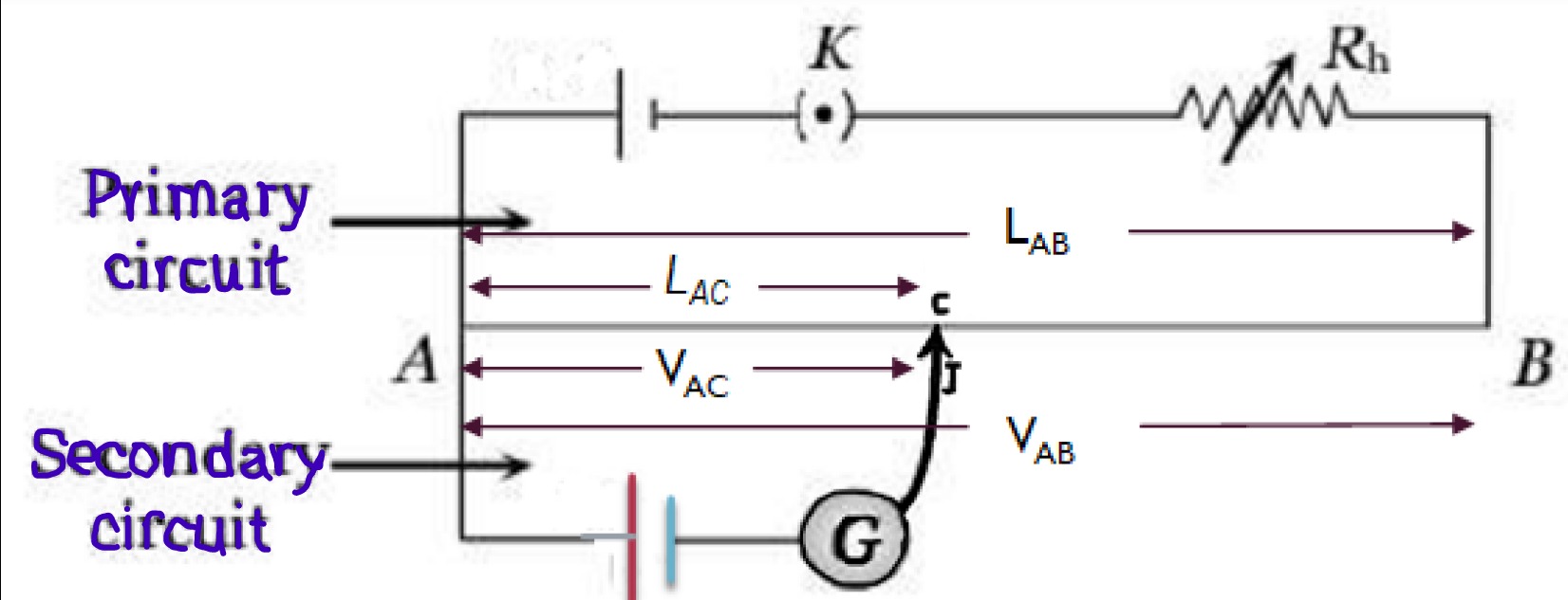
A stretched wire potentiometer consists of a 10m long wire uniform in cross-section which is made of tungsten or constantan and is laid parallel with each stretch 1m long on a wooden platform.
One end of this wire, say A, is joined to the positive terminal of the battery and the other end, say B, to the negative terminal of the battery via a key and a rheostat in series. When the key is closed a current flow through the wire AB and a certain p.d. is set up between A and B. Potential decreases uniformly along the wire from A to B.
PRINCIPLE OF POTENTIOMETER
“If a constant current is passed through the wire whose cross-section is uniform, the drop in potential(p.d.) across any length of the wire is directly proportional to the length.”
Consider a potentiometer as shown in the figure alongside.
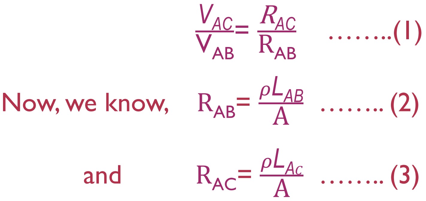
Let the length of the wire be LAB and the p.d. applied between two ends A and B of the wire is VAB and the resistance of this wire are RAB and the potential drop across a length LAC is VAC.
Then using the potential divider rule, we have
Here, 𝜌 is the resistivity of the potentiometer wire and A is the area of the cross-section.
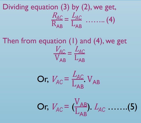
Here, the term inside the parentheses is the potential gradient which is the potential per unit length of the wire and is denoted by k. Its SI unit is Volt/m. Therefore, equation (5) can be written as:
Since the potential gradient is constant for a wire of given material, we have
i.e., the potential difference between A and C is directly proportional to the length of that section, which proves the principle of the potentiometer.
Applications of Potentiometer
There are many different uses of a potentiometer. The three main applications of a potentiometer are:
- Comparing the emf of a battery cell with a standard cell
- Measuring the internal resistance of a battery cell
- Measuring the voltage across a branch of a circuit
1. To compare the emf of two cells:
For this purpose, the two ends A and B of the potentiometer wire are joined to a battery (driving cell), a key, and a rheostat as shown in fig.
The positive terminals of the cells E1 and E2, whose EMFs are to be compared, are joined to point A. The negative terminals are connected to a two-way key whose middle point is connected to a sensitive galvanometer G and to a sliding contact(jockey).
The key K is closed, and a current is passed through the wire AB. First E1 is connected to the circuit by closing the key K1 with key K2 open and the jockey is slid gently over the wire AB to find the null deflection in the galvanometer.
Suppose the galvanometer shows null deflection at C1. If the length of AC1 is l1. Then, from the principle of the potentiometer,
Since in null deflection no current is drawn VAC1=E1, therefore, we have
Now cell E1 is disconnected and cell E2 is connected to the circuit through key K2 .Again a balancing length of the wire is found. Suppose its value is l2.
Now, dividing equation (1) by (2), we get
Observations are repeated with different currents through the wire by changing the position of the rheostat and the average is found.
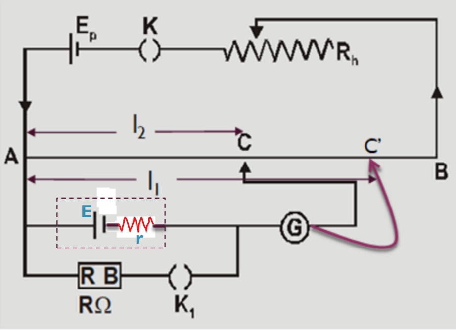
2. To Determine the Internal Resistance of a Cell:
To determine the internal resistance of a cell the circuit connection is made as shown in the figure. A battery, a key K, and a rheostat are connected to the potentiometer wire as a driving circuit.
Another circuit is prepared with cell E whose internal resistance is to be determined. A resistance box RB and a key K1 are joined in series.
The positive terminal of cell E is joined to point A of the potentiometer and its negative terminal is joined to the galvanometer and a jockey in series.
First, the key K is closed and the null deflection length is found on the potentiometer wire with K1 open( i.e. only cell E is connected ).
Let this length from A be l1.
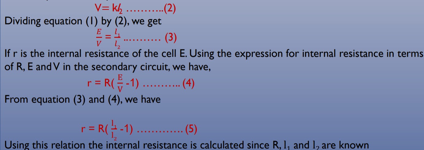
Where k is the potential gradient along the wire AB. E r A suitable resistance is taken from the resistance box and the key K1 is closed (i.e. the resistance box is also connected).
Let the null deflection length from A be l2. Since it is the balanced point for the p.d.‘V’ across the resistance used,
3.Measurement of Voltage by Potentiometer:
The idea behind using a potentiometer to measure the voltage across a circuit branch is equally straightforward. Here, we must first adjust the rheostat to change the current flowing through the resistor so that it results in a particular voltage drop per unit of resistor length.
The branch must now have one end attached to the resistor's base and the other end linked, via a galvanometer, to the resistor's sliding contact. The sliding contact on the resistor must now be moved until the galvanometer displays zero deflection.
Since we have already adjusted the voltage per unit length of the resistor, when the galvanometer reaches its null condition, we must read the position of the sliding contact tip on the resistor scale to determine the voltage across the branch of the circuit.

ADVANTAGES OF POTENTIOMETER OVER VOLTMETER
- The voltmeter cannot measure the correct value of EMF as it draws some current from the cell. The reading shown by the voltmeter will be TPD not EMF.
- If we use a potentiometer instead, the galvanometer shows null deflection in which no current is drawn from the cell and the cell is open in the circuit. As a result, the corresponding voltage will be EMF. So, the potentiometer is equivalent to an ideal voltmeter of infinite resistance.
- While taking a reading with a voltmeter deflection of the needle is read whereas with a potentiometer null deflection is taken. Therefore, the error in measurement with a voltmeter will be larger than with a potentiometer.
Galvanometer
A galvanometer is a device that is used to detect and measure feeble currents in electric circuits. It is also used to detect the direction of current in circuits.
A galvanometer is a very sensitive instrument that is used in null deflection measurement and is also used in making ammeters and voltmeters. In a circuit, it is depicted by the symbol
A galvanometer consists of a coil placed between two pole pieces of a magnet. When a current passes through the coil, it experiences torque, and the coil is deflected from its positions and so does the pointer needle attach to it.
The deflection is directly proportional to the strength of the current. The attached scale measures the deflection.
Shunt
A shunt is a very small resistance connected in parallel to the galvanometer coil. The value of the shunt is so chosen that the desired current passes through the galvanometer and the rest of the current passes through the shunt.
In another sense, a shunt is a current divider or a current bypass resistance.
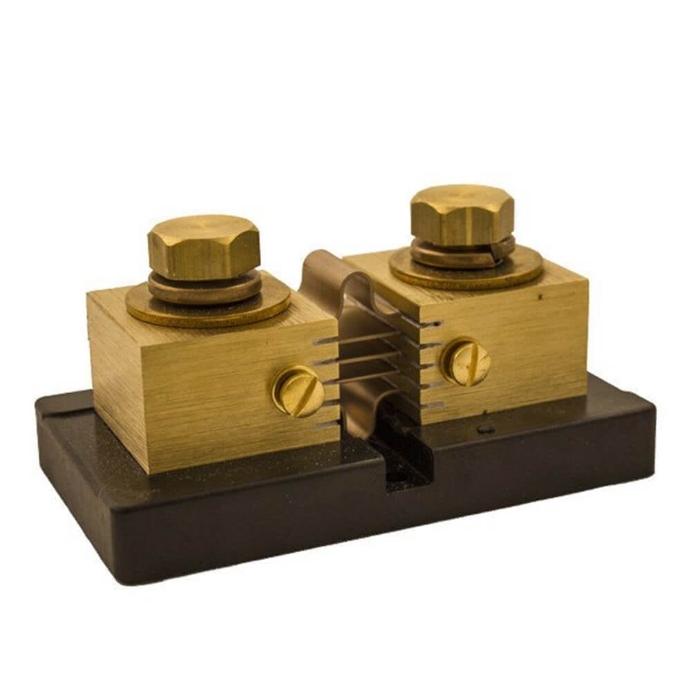
Uses Of Shunt A shunt in a circuit is used:
- To convert a galvanometer to an ammeter.
- To increase the current in a circuit.
- To increase the range of the galvanometer.
Ammeter
An ammeter is a low-resistance device that is used to measure electric current in a circuit. It is basically a galvanometer itself with a by-pass resistor of a small value connected across the coil.
Generally, an ammeter is connected with due considerations for polarities (+) and (-), depicted on the connecting terminals. Since an ammeter is used to measure the current in a circuit, it is connected such that all the current passes through it and hence it is always connected in series combination with the source.
As the coil resistance of an ammeter is minimal, the change in resistance caused by connecting it in a series combination is negligible. On the other hand, if, mistakenly, it is connected in parallel with the source it will appreciably reduce the resistance of the circuit, thereby, increasing the current and hence it cannot measure the current accurately.
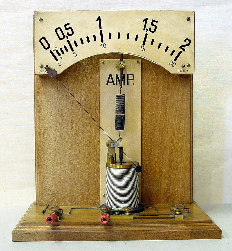
SQ. An ammeter is always connected in series. why?
VOLTMETER
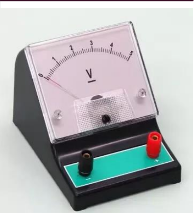
A voltmeter is a high-resistance device that is used to measure the potential difference between any two points in a circuit. Its construction is not much different from a galvanometer.
Usually, a calculated high resistance is joined in series with the coil of a galvanometer, which, then acts as a voltmeter.
- Since the function of a voltmeter is to measure the voltage between any two points in the circuit, say across a load, it is connected across that two points and hence the combination becomes parallel. Because of the very high resistance of a voltmeter, it doesn’t draw any current when connected in parallel and hence it measures the potential difference or voltage accurately.
- On the other hand, if a voltmeter is mistakenly connected in series, the resistance of a circuit increases appreciably thereby reducing the current in the circuit and hence it cannot measure the voltage accurately.
SQ. A voltmeter is always connected in parallel. Why?
CONVERSION OF A GALVANOMETER INTO AMMETER
We know that an ammeter is a low-resistance device, while the galvanometer has moderately high coil resistance. So, to convert a galvanometer into an ammeter the resistance must be reduced. This can be achieved by connecting a low resistance(called the shunt) in parallel with the galvanometer coil.
Consider a galvanometer of coil resistance Rg which can bear maximum current Ig to be converted to an ammeter of range(0-I) as shown in the figure. For this, let a shunt of resistance ‘S’ is to be connected in parallel with the galvanometer coil.
When connected, the current divides, and ‘Ig ’ passes through the galvanometer coil and the remaining current (I-I g ) through the shunt.
Since the shunt and the galvanometer coil are in parallel, we must have,
P.d. across galvanometer coil = P.d. across the shunt
This gives the value of the shunt which is connected in parallel with the galvanometer coil and works as an ammeter of the desired range.
The net resistance RA of an ammeter is then, given by:
Which is obviously less than the resistance of the shunt as desired.
CONVERSION OF A GALVANOMETER INTO VOLTMETER
We know that a voltmeter is a high-resistance device but the galvanometer has only moderate resistance. So, to convert a galvanometer into a voltmeter its resistance is to be increased, which can be achieved by connecting a very high resistance in series with the galvanometer coil.
The high resistance connected in series with the galvanometer coil is called the multiplier.
Suppose a galvanometer of coil resistance Rg that can bear maximum current ‘Ig ’ is to be converted to a voltmeter of range (0-V) volts as shown in the figure. Let, the multiplier be connected in series has resistance Rm. The same current passes through Rg and Rm. Therefore,
V = Ig (Rg + Rm)
Or, V / Ig = Rg + Rm
Or, Rm = ( 𝐕 / 𝐈𝐠 ) - Rg
This gives the value of the multiplier to be connected in series with the galvanometer coil and the combination works as a voltmeter of range(0-V)volts.
The expression shows that the value of the multiplier depends only on the range of voltmeter V because Rg and Ig are constants for a given galvanometer.
The net resistance of the voltmeter is: Rv = Rg + Rm
Ohmmeter
An ohmmeter is an instrument for measuring electrical resistance in a circuit.
In the simplest ohmmeters, the resistance to be measured may be connected to the instrument in parallel or in series. If in parallel (parallel ohmmeter), the instrument will draw more current as resistance increases.
If in series (series ohmmeter), the current will decrease as resistance rises. For high resistances, the scale is usually graduated in megohms (106 ohms), and the instrument is called a megohmmeter, or “megger.”
Here, we intend to discuss a series-Ohmmeter which consists of a meter, a resistor, and a source connected in series as shown in the figure.
The resistance R to be measured is connected between the terminals ‘x’ and ‘y’. The series resistance Rs is variable and is adjusted so that when terminals x and y are short-circuited (i.e. when R=0), the maximum current passes through the circuit and the meter shows full deflection. When the circuit is kept open at x and y (R=∞), no current flows in the circuit and the meter shows zero deflection.
For any intermediate value of R, the meter deflection lies between these two values and the meter scale can be calibrated to read the resistance R directly. Larger currents correspond to smaller resistances, so this scale reads in reverse as compared to the scales showing currents.
Potential Divider
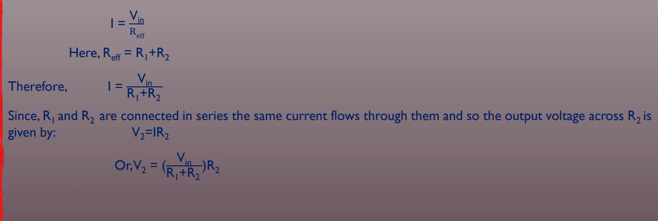
Two resistances connected in a series act as a potential divider. A potential divider is used when we require a lower potential difference between any two points in our circuit than the emf or voltage supplied by the source.
The potential divider divides the voltage or emf in the desired fraction. The circuit diagram for the potential divider is shown in the figure alongside.
The voltage supplied by the battery is 𝑉𝑖𝑛 and the total current in the circuit is given by
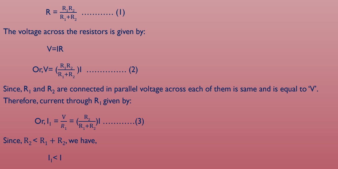
Current Divider
Resistances connected in parallel act as a current divider. Consider a current divider circuit consisting of two resistances R1 and R2 in parallel as shown in the figure alongside.
The source provides total current ‘I’ and the source voltage is ‘V’. The net resistance of the circuit is:

Superconductors
Those materials whose electrical resistivity drops suddenly to zero when the specimen is cooled to a sufficiently low temperature are called superconductors. This phenomenon is called superconductivity.
The temperature at which the resistance of the material suddenly falls to zero is called the critical temperature or the superconducting transition temperature and is denoted by Tc. For mercury Tc=4.2K.
This phenomenon was first observed by H. Kammerling Onnes in 1911.
The variation of resistance/resistivity of superconductors with temperature as compared to metallic conductors is shown in fig(1) below.
Flux Exclusion or Meissner’s Effect:
If a superconducting specimen is placed in a magnetic field and then cooled through the transition temperature for superconductivity, the magnetic field originally present is expelled out of the specimen. This phenomenon is known as flux exclusion or Meissner’s Effect.
According to this, the bulk superconductor in a magnetic field(weak) will act as a perfect diamagnet, with zero magnetic induction (B=0) inside it.
Two essential properties of superconducting states are:
- Perfect diamagnetism(B=0, Meissner Effect)
- Zero resistivity[ 𝜌 =0, E = 𝜌J=0 ]
Applications Of Superconductors
- (i) Superconductors form the basis of energy-saving power systems, namely the superconducting generators, which are smaller in size and weight, in comparison with conventional generators.
- (ii) Superconducting magnets have been used to levitate trains above their rails. They can be driven at high speed with minimal expenditure of energy.
- (iii) Superconducting magnetic propulsion systems may be used to launch satellites into orbits directly from the earth without the use of rockets.
- (iv) High-efficiency ore-separating machines may be built using superconducting magnets which can be used to separate tumor cells from healthy cells by high gradient magnetic separation method.
- (v) Since the current in a superconducting wire can flow without any change in magnitude, it can be used for transmission lines
PERFECT CONDUCTORS
A perfect conductor or perfect electric conductor is an idealized material exhibiting infinite electrical conductivity or, equivalently, zero resistivity.
While perfect electrical conductors do not exist in nature, the concept is a useful model when electrical resistance is negligible compared to other effects. For example, in electrical circuits, the connecting wires are supposed to possess no resistance.
Properties of Perfect conductors
- Perfect conductors have exactly zero electrical resistance- a steady current within a perfect conductor will flow without losing energy to resistance. Resistance is what causes heating in conductors, thus a perfect conductor will generate no heat. Since energy is not being lost to heat, the current will not dissipate; it will flow indefinitely within the perfect conductor until there exists no potential difference.
- Perfect conductors require a constant magnetic flux- the magnetic flux within the perfect conductor must be constant with time. Any external field applied to a perfect conductor will have no effect on its internal field configuration.
Difference between a perfect conductor and a superconductor
- i) Superconductors, in addition to having no electrical resistance, exhibit quantum effects such as the Meissner’s Effect and Quantization of magnetic flux.
- ii) Perfect conductors, by definition, have zero electrical resistance at all temperatures while superconductors have zero resistance only below a particular temperature called the critical temperature(which is material dependent).
- iii) In perfect conductors, the interior magnetic field must remain fixed but can have zero or non-zero values.
- iv) In real superconductors, all magnetic flux is expelled during the phase transition to superconductivity (The Meissner Effect), and the magnetic field is always zero within the bulk of the superconductor.
Joule's law of heating
when a current ‘i ' passes through a conductor of resistance ‘r’ for time ‘t’ then the heat developed in the conductor is equal to the product of the square of the current, the resistance, and time.
H=I^2×R×t ''
src: Toppr


